
Application-Based Selection
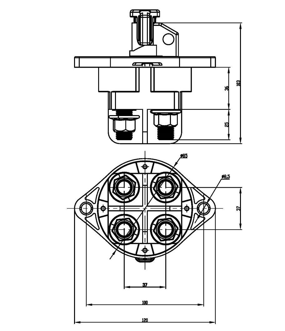
Check the model drawings and terminal configuration against your equipment before integrating the switch.
PRODUCT LINE / CUSTOM SOLUTIONS / TECHNICAL SUPPORT
OEM & Custom Solutions
Explore product specifications, application requirements and customization options for your equipment.
FOR OEMS / REF 20
Review the electrical ratings, connection options and installation details for this switch configuration.
Confirm the circuit ratings, switch positions, mounting dimensions and terminal connections for your application.
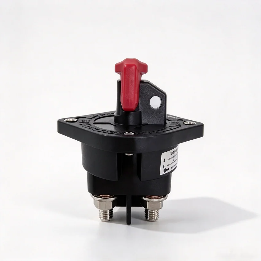
| Maximum continuous current | M12 terminal | Each circuit is 500A, (2 * 4/0 input and 2 *4/0 out cables) Each circuit is 350A ,(2 * 4/0 input and 2 * 4/0 out cables) | |||
|---|---|---|---|---|---|
| M10 terminal | Each circuit is 400A, (2 * 4/0 input and 2 * 4/0 out cables) Each circuit is 280A ,(2 * 4/0 input and 2 * 4/0 out cables) | ||||
| Maximum current for 30 seconds | M12 terminal | Each circuit is 2250A ,(2 * 4/0 input and 2 * 4/0 out cables) Each circuit is 1750A, (1 * 4/0 input and 1 * 4/0 out cables) | |||
| M10 terminal | Each circuit is 1800A ,(2 * 4/0input and 2 * 4/0 out cables) Each circuit is1400A ,(2 * 4/0 input and 2 * 4/0 out cables) | ||||
| Surge rating (1seconds) | M12 terminal | Each circuit is 3000A ,(2 * 4/0 input and 1*2AWG cable) | |||
| M10 terminal | Each circuit is 2400A ,(2 * 4/0 input and 1*2AWG cable) | ||||
| Intermittent rating | M12 terminal | 2250A*30 seconds (2 * 4/0 input cable) | |||
| M10 terminal | 1800A*30 seconds (2*4/0 input cable) | ||||
| Climatic environment test | High and low temperature operation | -30℃ ~+70℃. During and after the test, all functions of the device/system meet the design requirements. | Mecha -nical Enviro -nmen -t test | Sinusoid al vibration | It meets the requirements of GB/T2423.10-2008 after the test. |
| High and low temperature storage | From-40℃ to+80℃, one or more functions of the device/system can't meet the design requirements during the test, but all functions should be able to return to normal operation after the test. | Random vibration | It meets the requirements of GB/T2423.10-2008 after the test. | ||
| Class of protection | IP 67 Protection against dust inhalation (overall protection against contact and dust penetration) Protection against short-term immersion (anti-immersion) | Mechani cal impact | It meets the requirements of IEC 60068-2-27:2008 after the test. | ||
| Salt spray resistance | One or more functions of the device/system in the test do not meet the design requirements, but all functions should be restored to normal operation after the test. | Crash test | It meets the requirements of GB/T 2423.6-1995 after the test. | ||
| Transient immunity along power line | In accordance with ISO7637-2 | Operating moment | 0.5N·m~2N·m | ||
| Electrostatic discharge immunity | In accordance with GB/T 28554-2012 | Mounting hole | Ø8.5mm | ||
| Mechanical strength | ≥18N·m | Terminal size | M10/M12×25 | ||
| DC voltage bearing experiment | See Appendix 1 and 2 for detail | Life requirement | 1000 times (in accordance with UL-SUBJECT-1107-2002) | ||
Please refer to the technical datasheet for the exact ratings and operating conditions of each model.
TECHNICAL DRAWINGS
Open a figure to inspect the dimensions and configuration details.
Check the model drawings and terminal configuration against your equipment before integrating the switch.
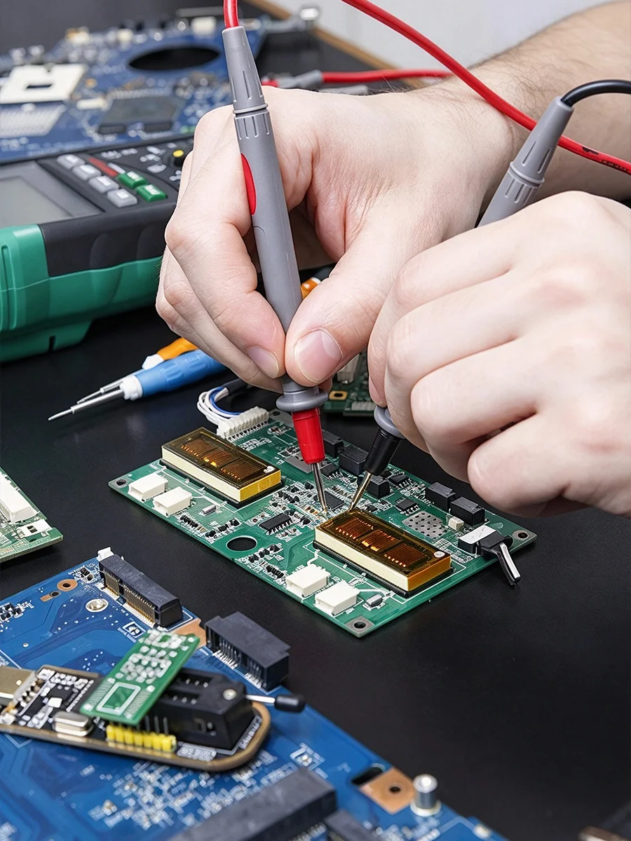
Confirm the circuit ratings, switch positions, mounting dimensions and terminal connections for your application.

Discuss your application, technical parameters and installation constraints with our team. Available options depend on the product platform, engineering feasibility and order requirements.
Check the model drawings and terminal configuration against your equipment before integrating the switch.
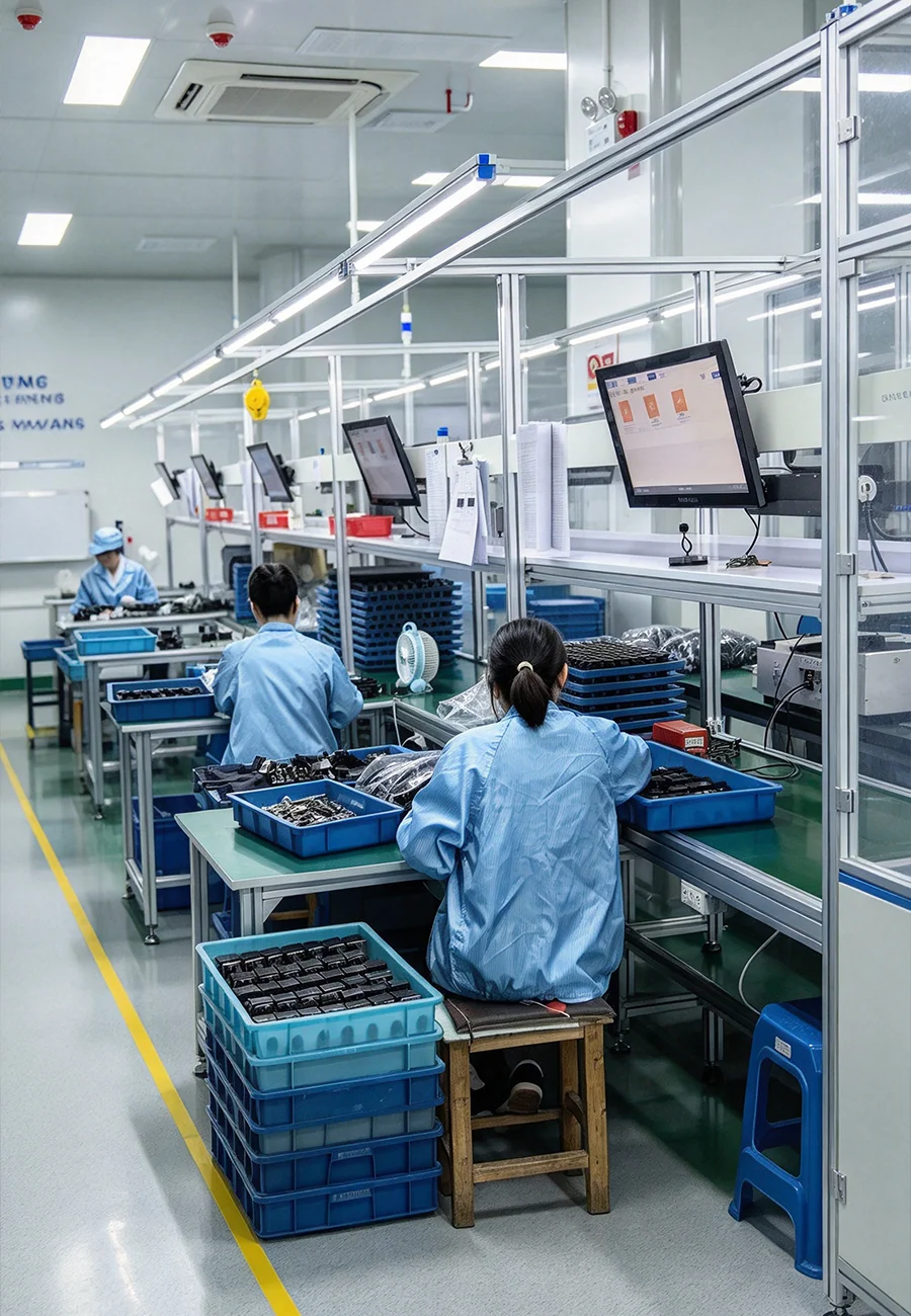
For equipment manufacturers, consistent specifications and reliable supply arrangements are important throughout the product lifecycle.
When evaluating a supplier, consider technical documentation, sample verification, production consistency, customization feasibility and long-term sourcing requirements.
FAQ
Send us your specifications, drawings or existing part number to discuss product suitability, customization feasibility and quotation requirements.
Request a quoteConfirm the circuit ratings, switch positions, mounting dimensions and terminal connections for your application.
Customization depends on the model and technical requirements. Share your specifications or drawings so the feasibility of your requested configuration can be reviewed.
Sample availability, cost and lead time should be confirmed for the selected model before placing an order.
Provide the model number, required quantity, electrical specifications, intended application and any special technical or packaging requirements.